TR-606 / 808 bass drum circuits
Posted on June 27, 2021 by JulianBackground
The TR-606 and TR-808 were drum machines sold in the early 80s, that used analog circuits to produce their instrument voices. Many reimplementations of the original circuits exist (both as commercial and DIY projects, but mostly of the 808), likely due to their iconic sound and the public availability of circuit schematics from the devices’ service manuals.
Despite this, it is hard to find online information on how the circuits produce their sound, beyond the basic principles of operation. 1
These drum circuits are particularly interesting because the core idea of the circuit is easy to understand, but there are various complexities that affect the final output sound (especially in the case of the TR-808). This post is an analysis of the important aspects of the bass drum circuits from both devices.
The general idea behind both circuits is to simulate an drum directly with a circuit that will oscillate in response to being “hit” with a voltage pulse. 2 To do this, one needs to produce a circuit that will have a pair of complex conjugate poles, which corresponds to an impulse response with oscillatory behavior.
The Bridged-T Circuit
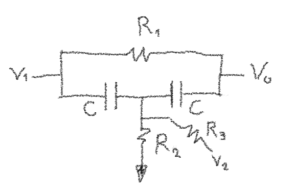
The core of both machines’ bass drum circuits (and many of the other drum voices) is the following bridged-t circuit:
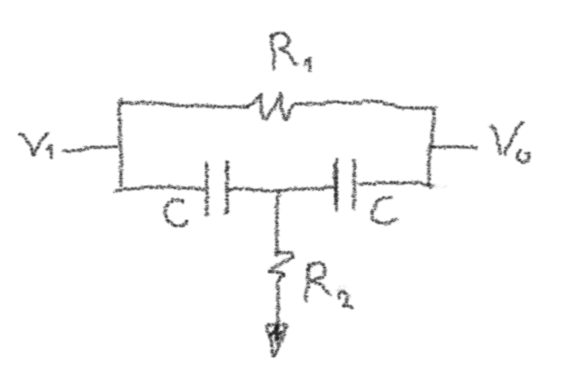
Without going through the derivation, the transfer function of the circuit is:
On its own, this circuit does not have complex poles, since it is a passive RC circuit. However, it does have complex zeros. Given a way to turn zeros into poles, the desired resonant behavior can be achieved.
TR-606 Bass Drum
The TR-606 bass drum circuit is the simplest extension of the bridged-t circuit:
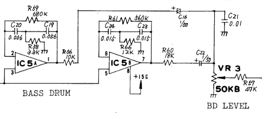
Op amps IC5A and IC5B have the bridged-t connected from the output to the inverting input (i.e. as negative feedback).
Why does this work ? In general, if an amplifier is connected with negative feedback, and the gain is large enough (loop gain much larger than 1), then the resulting transfer function is the reciprocal of the feedback transfer function. This has the effect of exchanging the poles and zeros of the feedback transfer function. In the context of the bridged-t, this is how the complex zeros are turned into the desired complex poles.
This circuit (bridged-t in the feedback path of an opamp) is what is presented in the TR-808 service manual as a simplified explanation – apply a pulse and get a drum sound:
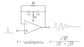
It is often referred to online as a bandpass filter (maybe because one would expect a bandpass filter to be used as a resonator), but this is a misleading label.
The transfer function from the opamp’s input to its output is: 3
A second order bandpass should only have an term in the numerator. Instead of a bandpass effect, this function will still have unity gain at DC and at high frequency. The bode plot for this transfer function looks like the following:
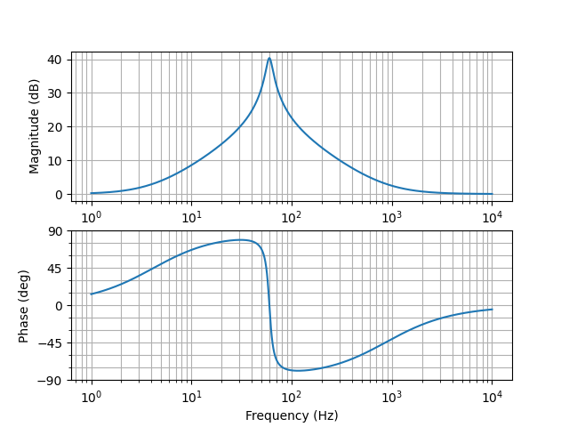
Based on this plot, it is apparent that while this circuit does have resonance at its natural frequency, it does not attenuate any other frequencies (note the y-axis, the lowest value is 0 dB – unity gain). As a consequence, the trigger pulse is fed through to the output. This feature is very important to the sound of the circuit, but isn’t usually mentioned.
Although the feedthrough of the trigger pulse seems like a disadvantage, it can be helpful when trying to simulate a drum – hearing both the hit and the response to it is presumably more realistic than mostly hearing the response. 4 This was probably done on purpose, since the TR-808 circuit shows a way to get a true bandpass from this circuit (more on this later), but this wasn’t used in either circuit for the trigger input.
TR-606 Trigger Circuit
Since the trigger pulse is not isolated from the audio signal, it is worth examining what it looks like.
The trigger circuit actually has two inputs, one that I’ve annotated as “Accent” (the exact name from the manual), and one that I’ve annotated as “Enable” (usually labeled in the manual with the name of the instrument being triggered):
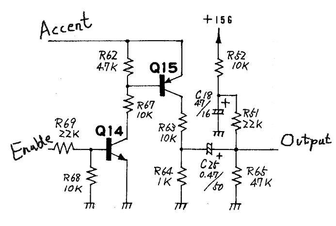
Both inputs are required to get an output, the enable input turns on Q14, which pulls down the base of Q15 to turn it on, but the accent input needs some positive voltage for this to happen. Effectively, this forms an AND gate.
This circuit has two advantages that relate to controlling many different sounds at the same time.
It’s difficult to send a pulse to each instrument that will play on a beat at the same time (the triggering is microprocessor controlled). Having two inputs solves this problem, each instrument that will play can be enabled before the beat, and then the same pulse can be sent to all accent inputs on the beat, triggering only the instruments that were enabled.
The output amplitude is set by the amplitude of the accent input (when Q15 is in saturation, its collector will be ~0.3 volts lower than the voltage on the accent input). This allows for emphasis of certain beats (by using a larger pulse to make instruments playing on them louder), without needing software control of output volume.
From the purpose of analysis, assume a pulse is produced at the collector of Q15. This pulse is reduced by a factor of 11 by the R63-R64 voltage divider, and capacitively coupled to the output through C25. The static output level is set by the R52-R51-R65 voltage divider to around 9 volts. This is because the TR-606 does not have a negative supply like the TR-808, so the output needs to be about midway between 0 and 15 volts to allow the op amp to swing in both directions (remember that the gain is unity at DC, so the input voltage sets the output voltage).
This is a simplified explanation since C25 (along with the resistors) will produce a highpass effect. Simulation can be used to find the actual pulse shape: 5 6
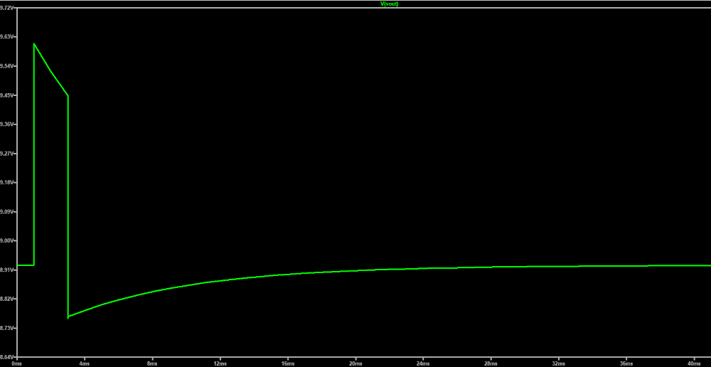
Given this trigger pulse, it can be fed to a time domain simulation of the bass drum transfer function, to get an idea of what the output would look like:
![]()
The upper graph shows the two resonators separately, and the bottom graph is a weighted sum similar to how the audio output is made. The higher frequency resonator was designed with faster decay, so that it mostly affects the start of the note. The feedthrough of the triggering pulse is also visible.
TR-808 Bass Drum
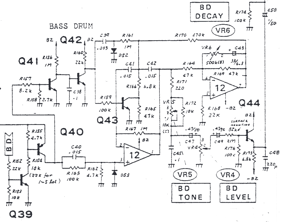
The TR-808 circuit is more complex than the one from the TR-606. It uses only one resonator, but adds several features: 7
- Adjustable decay time.
- Switchable doubling of the resonant frequency.
- Mid-note retriggering.
Adjustable decay time
To understand how the decay time can be adjusted, it makes sense to start from this modification of the bridged-t, which includes a second input:
Introducing to refer to the parallel combination of and , the transfer function from input is the same as before, but with rather than .
The transfer function from the input is:
Removing the parts of the circuit that aren’t immediately relevant to the adjustable decay leaves the following:
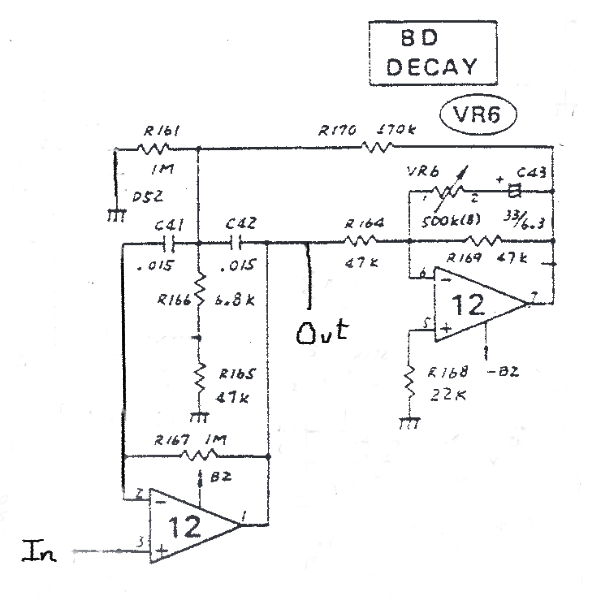
It should be possible to recognize the bridged-t circuit. R166 and R165 form and R170 is . R161 can be added in parallel with or just ignored since it is somewhat large (the exact component values don’t matter to understanding how the circuit works, and treating it as grounded is an approximation anyway).
Like in the 606 circuit, the input of the bridged-t is connected to the output of the opamp. Additionally, the second op amp forms an inverting amplifier connected between the output and the input of the bridged-t. As a signal flow graph, this looks like the following (where K is the gain of the inverting amplifier):
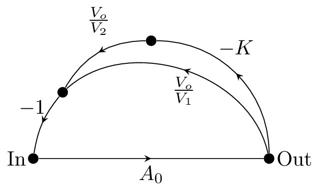
The same logic applies as before: since the op amp gain is large, the resulting transfer function is the reciprocal of the feedback transfer function. The feedback transfer function is the sum of both parallel feedback paths: 8
The gain of the feedback op amp changes the coefficient of s in the denominator, which affects how close the poles are to the imaginary axis, and therefore how fast the oscillations decay. If the coefficient gets to 0, the system will be unstable, so with and , this puts the upper limit for K at just under 1. This corresponds closely to the range of adjustment of the decay potentiometer, VR6, which allows adjustment of the (AC) gain of the feedback opamp.
The decay adjustment effect can be confirmed with time-domain simulation of the transfer function at various values of K:
![]()
Switchable doubling of the resonant frequency
Here’s what the service manual has to say about this:
Immediately after a trigger pulse is fed into the generator, the filter’s time constant – when ACCENT is present – is halved and has a resonance on twice its inherent frequency for a half cycle period, then on the fixed frequency with decaying amplitude. This changing frequency will sound a punchier crisp bass.
The mechanism is fairly easy to understand, Q43 is placed to effectively short out R165 when turned on. While R165 is shorted, the resistance is only R166, so the resonant frequency is increased.
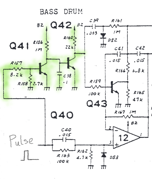
Q41 and Q42 act to extend the pulse duration to control how the long Q43 is enabled for. The trigger pulse enables Q41, which pulls down the base of Q42, turning it off. When Q42 is off, the base of Q43 is pulled up by R160, turning it on. After the trigger pulse ends, C38 needs to charge through R156 in order for Q42 to be turned back on. This charging time controls how long the frequency doubling is enabled for.
There is another effect related to this circuit: a bass drum note from the TR-808 apparently drifts slightly lower in frequency as it decays. When the voltage at the collector of Q43 is negative, the base-collector junction is forward biased and the transistor will conduct slightly in the reverse direction. 9 Because of this, there is some leakage current during part of the output cycle, which can be thought of as a slightly lower resistance. This current depends on the amplitude at the collector of Q43, so as the note decays the effect is lessened, and the frequency approaches the theoretical value from the transfer function. 10
Mid-note retriggering
Also from the service manual:
When Q42 turns on after 4ms, current discharging from C39 via R161 produces a retriggering pulse. At this time the generator oscillates on the inherent frequency.
The interesting part is that this retriggering pulse is not on the same input as the initial pulse. Instead, it is applied via R161 to the central node of the bridged-t. Assuming for simplification that the other side of R161 (with C39) can be modeled as a voltage source, the retriggering pulse is input in much the same way as the feedback: via a resistor in parallel with .
In terms of the signal flow graph, with being the retrigger input, this looks like the following:
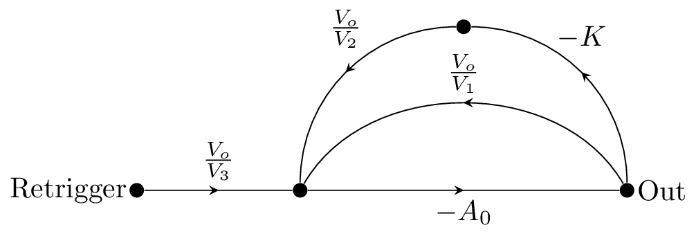
This is the previous transfer function in series with the one from to the inverting input. 11 Letting be the input resistor for the retrigger input (R161), the full transfer function is:
This transfer function actually describes a bandpass filter, 12 unlike the one from the normal trigger input. This makes sense since having the a pulse feed through in the middle of the note is much more of a problem than at the start – there’s no way that it would seem realistic. As mentioned previously, this also shows that the pulse feedthrough of the initial trigger was likely a desired effect, since this topology could have been used to avoid it.
Conclusion
Many interesting aspects of these circuits that are not commonly mentioned are relatively straightforward to analyze from an analog circuit/control theory perspective. My suggested key takeaways for building TR-606/TR-808 inspired designs are:
The bridged-t core of both circuits is not a bandpass as is sometimes claimed. Attention should be paid to the pulse that is driving the circuit, it will be heard in the output.
It’s easy to add extra inputs in parallel with the grounded resistor in the bridged-t for features like the decay adjustment feedback loop or retriggering.
A side effect of including the transistor for switchable frequency doubling is a subtle pitch drift as the note decays. It takes relatively little leakage current to cause this effect.
There is a paper on building a digital model of the TR-808 bass drum, which also provides a really good reference for some of the math. I’m hoping here to instead provide a description from an analog design perspective of how the circuits work and what details are significant to the sound. ↩︎
This is in contrast with the other main analog circuit method of producing a drum sound by having an oscillator that is on continuously and controlling the volume to shape individual notes. ↩︎
As mentioned, this is just the reciprocal of the previous transfer function. ↩︎
An interesting example: the Korg Volca Beats, a modern drum machine that uses analog voicing, has a “click” knob that controls how “clicky” the bass drum sounds. This suggests they are modifying the shape of the input pulse to change the sound. ↩︎
It is hard to find exact documentation of the trigger pulse width, other than a general consensus of a “few” milliseconds. The modeling paper says 1 millisecond for the TR-808. This was simulated with a 2 millisecond pulse as an example. ↩︎
It is worth noting that C18 has minimal impact on the output pulse shape, so was likely included for other reasons (such as filtering out noise from the power rail). ↩︎
The trigger circuit keeps the same two transistor input circuit, but the pulse shaping circuit after is different, and will produce a different pulse. I’ve neglected to reanalyze it here since there wouldn’t be much extra to discuss. ↩︎
The in the graph represents the connection to the inverting input. It is not part of the feedback transfer function in this definition. ↩︎
A bipolar transistor can operate reversed (i.e. with the roles of the collector and emitter interchanged) at significantly reduced performance.↩︎
The modeling paper instead attributes this frequency drift to leakage through R161 turning Q43 slightly on, but based on simulation, R161 is not required to produce this effect. When the collector is brought negative, base current can flow through R160 and R159.↩︎
Technically it’s the negative of the previous transfer function that’s in series, since the forward path is now also through the inverting input. This just requires multiplying it by . ↩︎
In fact, if you ignore the extra feedback loop used for the decay adjustment, this is just the multiple feedback bandpass topology. ↩︎